Project Motivation: Compact locking solutions for e-scooters, bikes, and those ankle-busting Razor scooters typically don't have a reliable means of communicating to others or their owners if they've been stolen. Traditional U-locks may be hard to break, but lack true peace of mind as owners only find about about their status upon return. By providing an alarmed, app-enabled smart lock, Mount Locks hopes to bring better security for these mobility products.
Project Goal: Build a mountable, prototype locking system that, upon cord-cutting or forceful pulling of the device, triggers a loud alarm and communicates status (unlock/lock/cut) to a user's phone, alerting in real-time.
Personal Objective: As the Lead EE on the project, assess electrical scope, define requirements/specifications, prototype the hardware via breadboarding, and in conjunction with product design (PD), design and integrate the printed circuit board (PCB) and other electronics into the system.
Electronics: Primarily system integration of an ATmega328P MCU chip & on-board ISP header for programming, FETs to trigger the alarm (speaker) and locking mechanism (solenoid), Bluetooth Low Energy (BLE) and battery management development boards from Adafruit, a Li-Po battery, a color-programmable LED ring, the cord itself, and an NFC breakout board from Seeed Studio that is enabled in hardware for a future revision. Upverter was the CAD software that I used.
Check out this paper that I wrote on the electrical hardware design by clicking here.
Electronics Bill of Materials (BOM) can be found by clicking here.
The video above shows the demo of Mount Locks. We hit 94dB (measured by my Apple Watch)! That's above city background noise of 60dB and nearby traffic/subway noise of 85dB (source), which means that stealers can't rely on being quiet to save them.
The video above shows the breadboarded version of the smart lock. It's pretty loud, so lower the volume first before playing!
The video above shows the PCB and electrical components working as expected before we assembled the device. It's also very loud -- this alarm is no joke!
The video above is a little fun we had, starring the computer engineer for the project, Jacob Londa. Since we could control the pulse width to the speaker, we could play some music while we worked!
The image to the right shows the final assembly of the system. The mechanical assembly is 3D printed, and the electronics are housed inside.
The image to the right is the electrical assembly and mechanical enclosure of the system, before the inner rigid back plate and other insulating material used to separate components are built in.
The image to the right is the partial assembly of the electronics before building it into the rest of the system. With the battery (not shown), we could verify that the electronics worked before full assembly.
The image to the right is the top layer of my PCB, fab'd by Sunstone Circuits. Quick turnaround, so fairly expensive but generally decent quality for small-scale designs. No issues found during bring-up.
The image to the right shows the CAD design of the top layer of my PCB. Upverter, now bought by Altium, has robust support for collaboration (for free!), and has been the default choice of mine for team projects like this one.
The image to the right shows the CAD design of the bottom layer of my PCB. It's mostly a ground pour, with a few of the more sensitive signals routed here.
The image to the right shows the locking mechanism up close. The cord itself is actually a flexible mechanical cord and an electrical wire wrapped together, and when the cord tip (pogo pin) touches the copper plate inside, a signal is relayed back to the MCU to let it know that the cord is plugged in. Then, the locking mechanisms (white pieces) can engage with the turn of a solenoid and keep the cord tip in place.
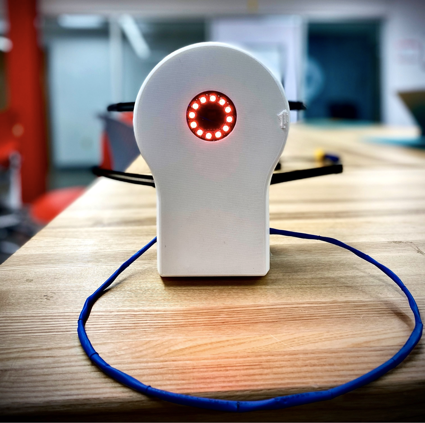 The image to the right shows the final assembly of the system. The mechanical assembly is 3D printed, and the electronics are housed inside.
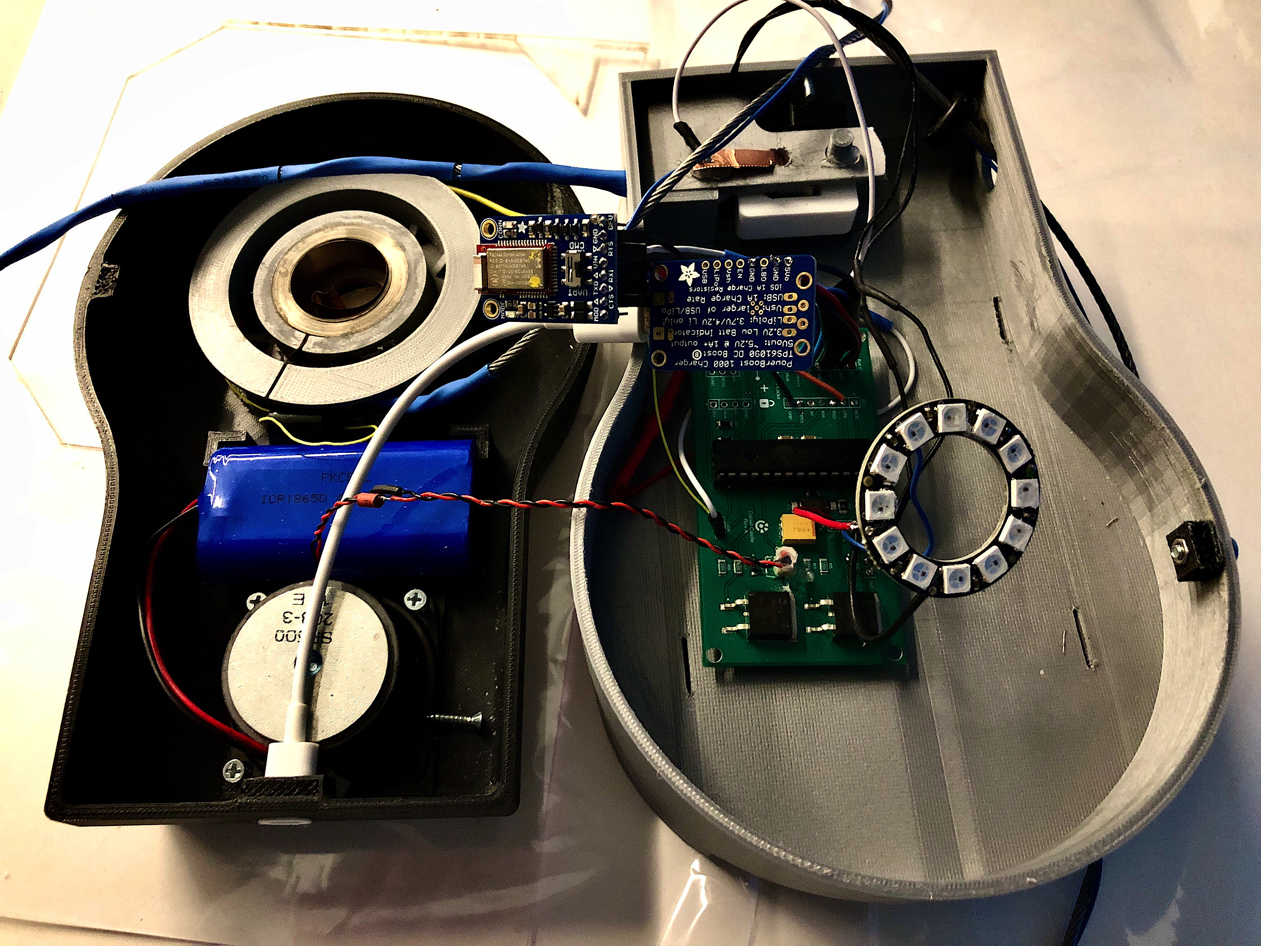 The image to the right is the electrical assembly and mechanical enclosure of the system, before the inner rigid back plate and other insulating material used to separate components are built in.
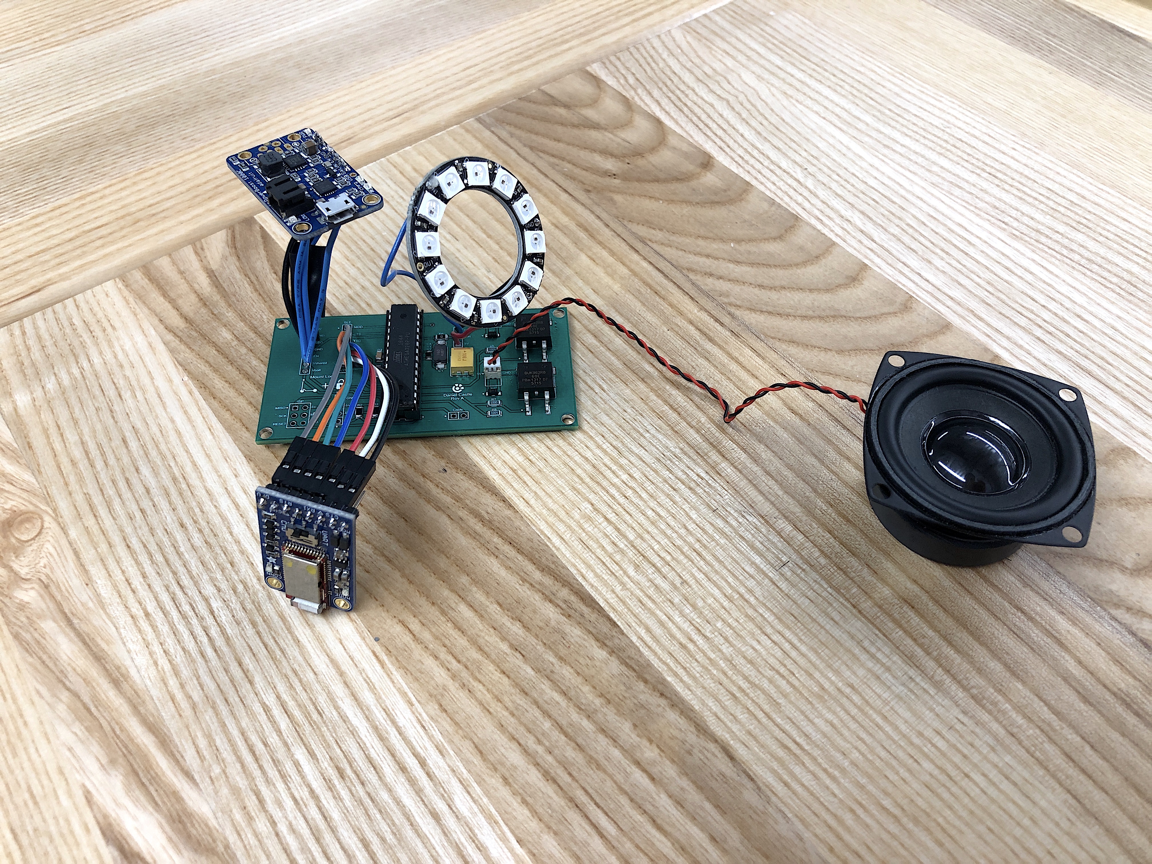 The image to the right is the partial assembly of the electronics before building it into the rest of the system. With the battery (not shown), we could verify that the electronics worked before full assembly.
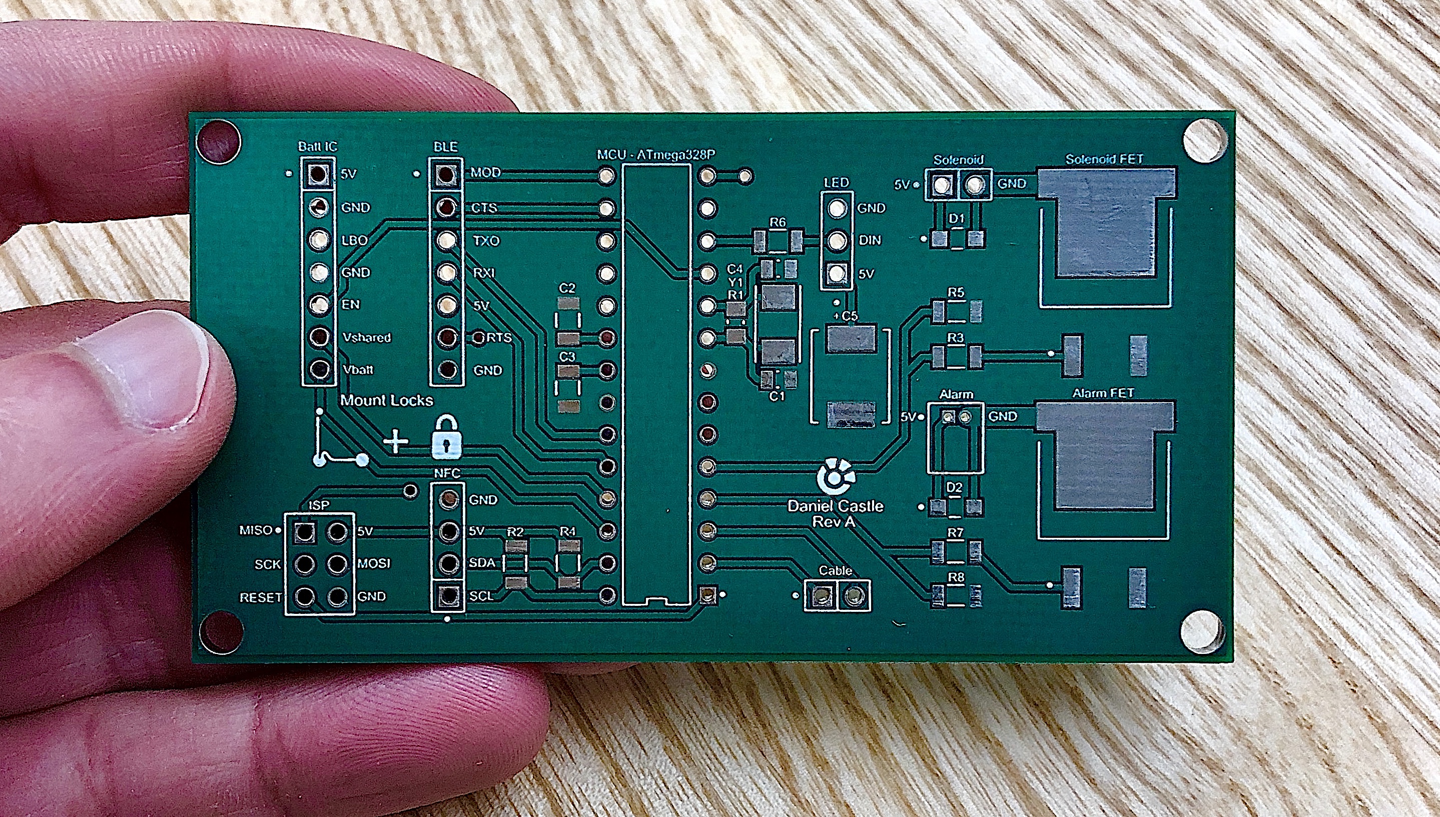 The image to the right is the top layer of my PCB, fab'd by Sunstone Circuits. Quick turnaround, so fairly expensive but generally decent quality for small-scale designs. No issues found during bring-up.
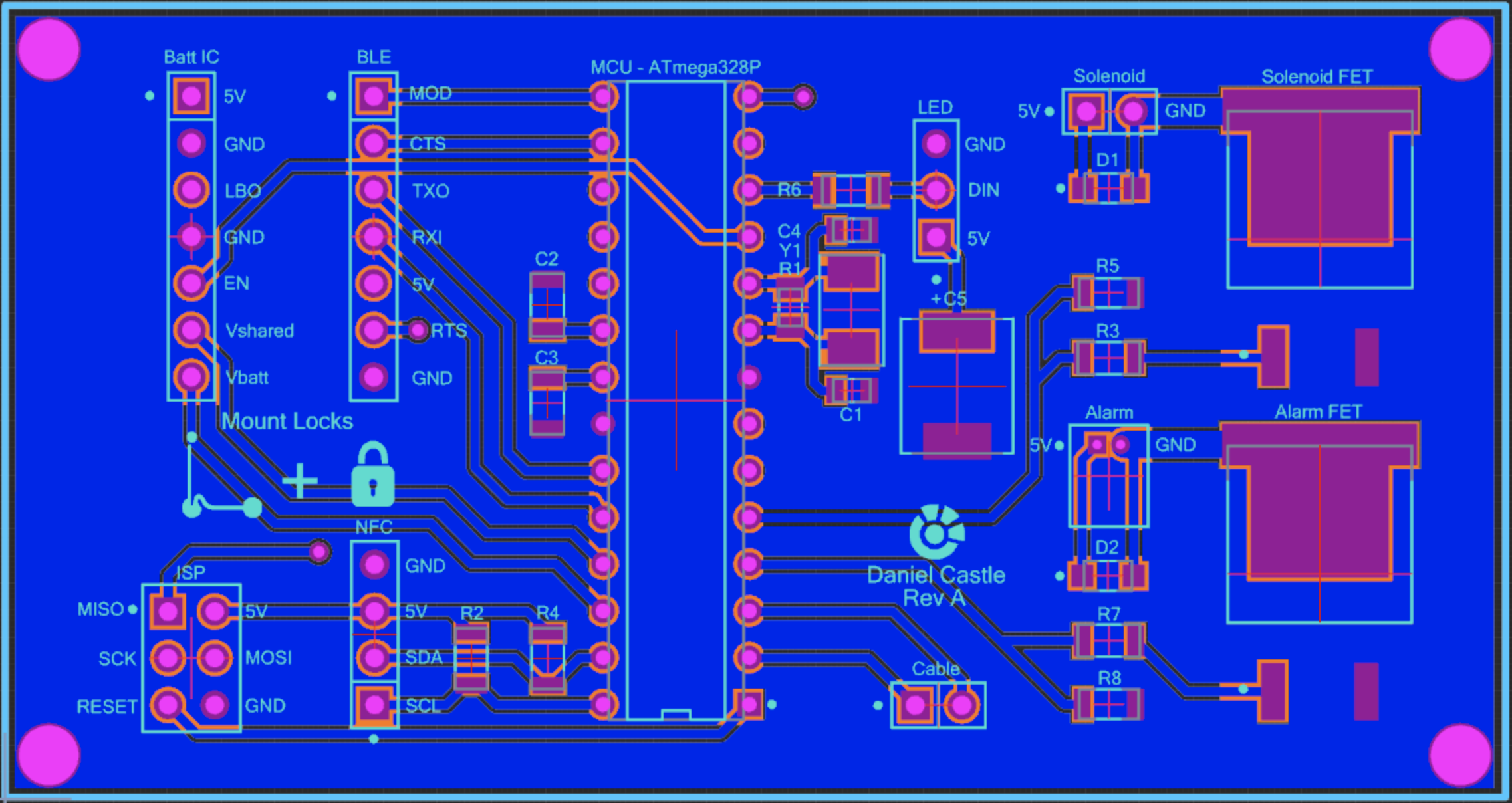 The image to the right shows the CAD design of the top layer of my PCB. Upverter, now bought by Altium, has robust support for collaboration (for free!), and has been the default choice of mine for team projects like this one.
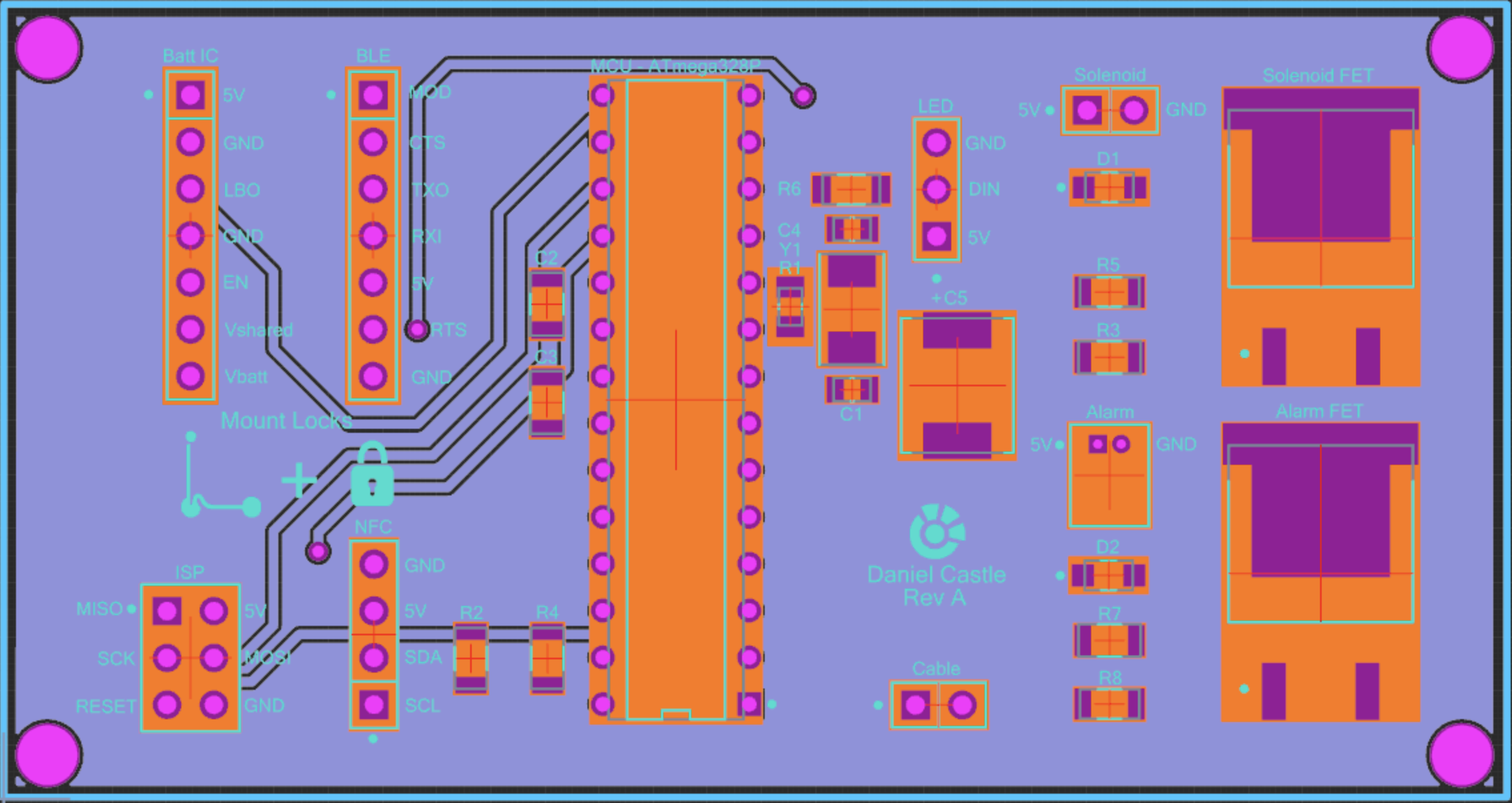 The image to the right shows the CAD design of the bottom layer of my PCB. It's mostly a ground pour, with a few of the more sensitive signals routed here.
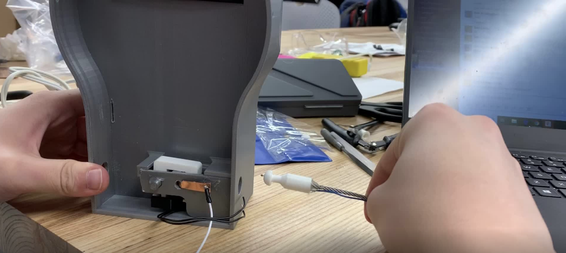 The image to the right shows the locking mechanism up close. The cord itself is actually a flexible mechanical cord and an electrical wire wrapped together, and when the cord tip (pogo pin) touches the copper plate inside, a signal is relayed back to the MCU to let it know that the cord is plugged in. Then, the locking mechanisms (white pieces) can engage with the turn of a solenoid and keep the cord tip in place.