SizeU
A Smart Measuring Device to Help Young Professional Women find Clothing that Fits Them Best
Personal Objective: To design and rapid prototype the circuitry necessary to send measurement information using Bluetooth Low Energy to a phone, in order to use that information in the future to select the best-fitting dresses, pants, and shirts for professional women who are shopping online.
Skills learned: Soldering, Arduino implementation, Bluetooth Low Energy incorporation, and Material Selection of Parts
Additionally, Early-stage product design, customer validation, and product prototyping experiences were integral to the project.
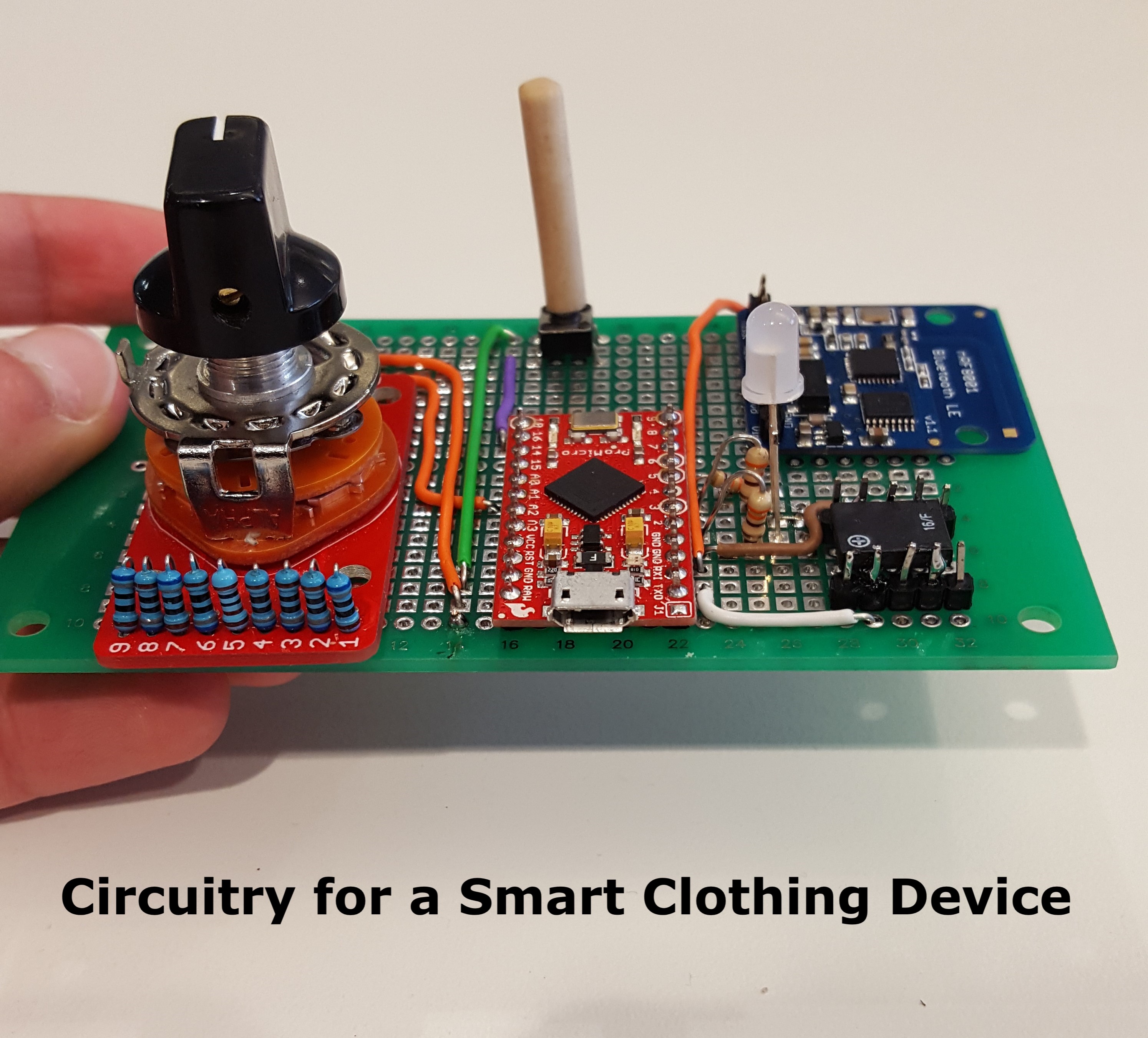
In the image above, the final circuit of this project's prototype is presented and is explained further below.
Check out this PDF for more information about the project by clicking here.
The complete code can be found here, written in Arduino.
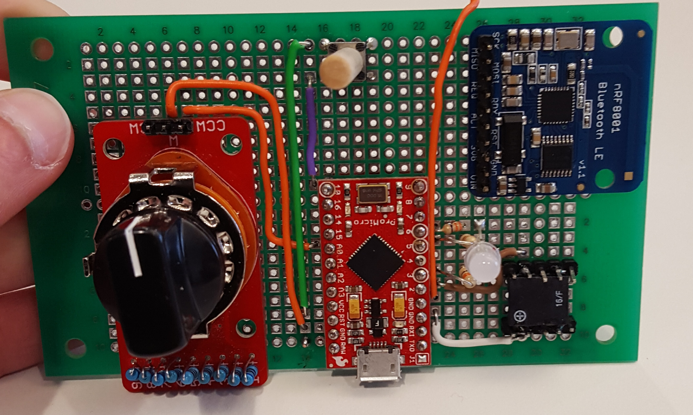 The image to the right shows the final circuit of this prototype.
On the upper right, a Bluetooth Low Energy (BLE) chip made by Adafruit was configured to send messages to a cell phone with the Adafruit-supported BLE app installed.
In the top of the image, a push button (attached to a wooden dowel for easier pressing) signaled when a measurement was to be sent.
On the left of the image, a rotary switch was implemented to select the measurement that the user was taking. The options for neck, waist, wrist, arm length, chest, and inseam were incorporated here.
In the center of the image, an Arduino Mini was used to drive all of the action.
On the bottom right of the image, an LED was used to indicate measurements that were successfully sent, currently sending, or failed to send.
On the bottom right of the image, a buzzer was used to indicate when power was turned on or off.
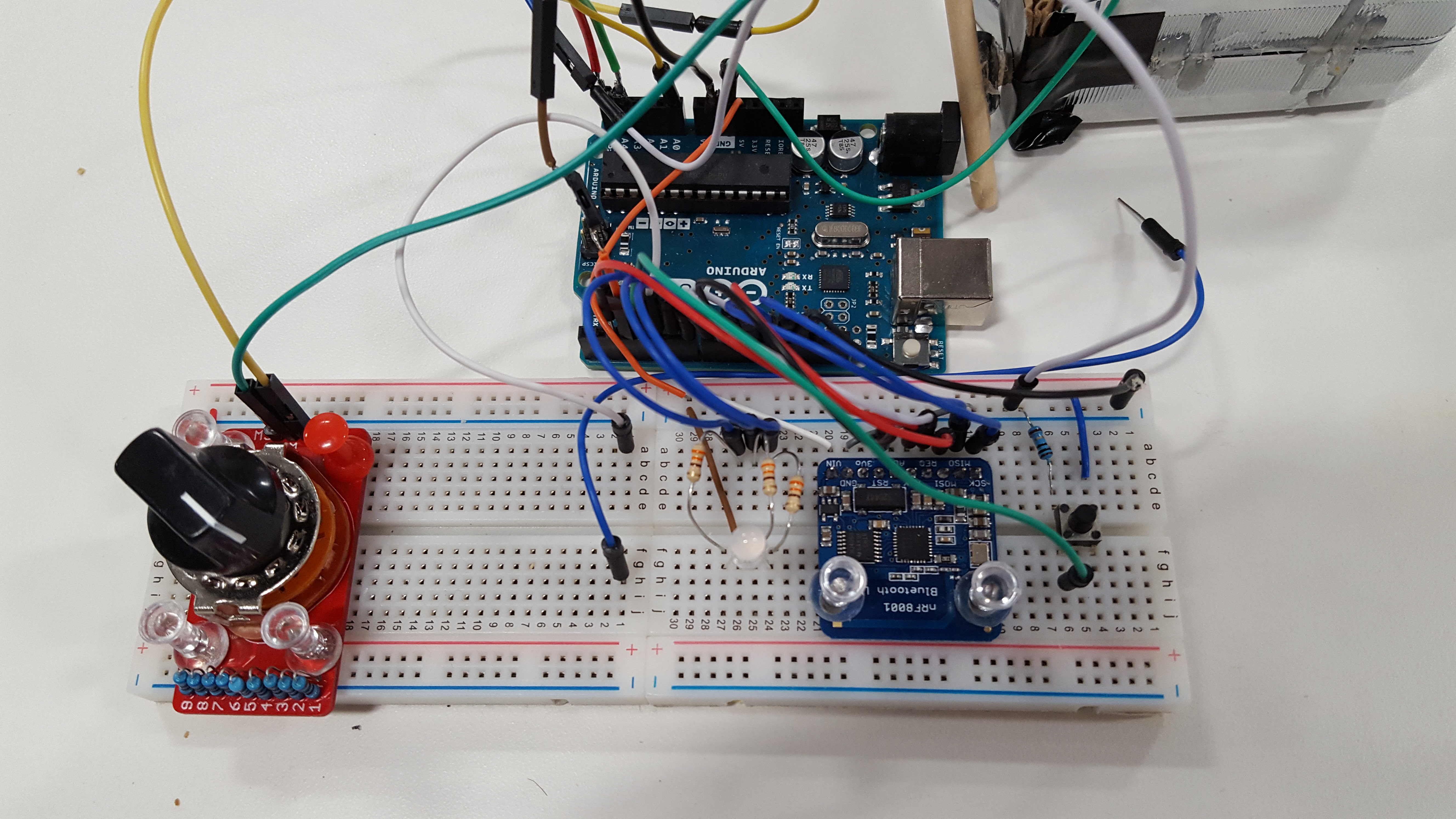 The image to the right shows the works-like prototype of this project.
In the top of the image, the Arduino Uno board is shown, with the various pins connected to the switch, the RGB LED, the Adafruit BLE chip, a pushbutton, and the rotary encoder inside of the tape measure on the upper right.
I prototyped the device on a breadboard primarily, with the jumpers wiring everything together.
To develop the works-like model, I added each component one-by-one, increasing the usability of the device with each iteration.
Once the first component was correctly tested and verified to work, I would move on to the next one. In this way, the project grew in scope and capability over time, with as minimal downtime or time spent debugging as possible.
When the prototype was complete, I moved everything to the final circuit board. After determining how many pins were needed, I chose the Arduino Mini as the MCU and soldered it and the remaining components to the board.
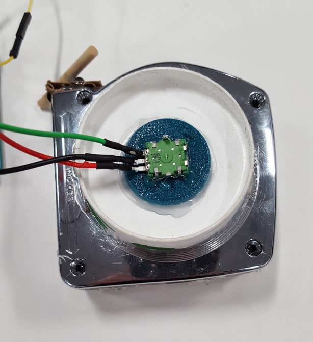 The image to the right shows the rotary encoder housed inside of a tape measure.
One of my team members created this part of the project, which is included here to form a complete picture of the project.
He redesigned the tape measure by adding a rotary encoder as the release mechanism of the tape and swicthing out the tape istelf for a more skin-friendly one, keeping only the housing the same.
As the tape is released, the spool of tape gets smaller, meaning that less tape is released per rotation of the rotary encoder.
By using an equation relating the position information to the size of the spool, he could accurately pick out how far the tape was released.
In the center of the image, the three leads coming out of the encoder are shown.
They go to the Arduino MCU, which uses their information to register the length of measurements.
Once that length is obtained, it is sent via Bluetooth Low Energy to a cell phone - that's the part that I worked on!