Advanced Imaging Technology Lab, ALERT (Dept. of Homeland Security Center of Excellence)
Research Assistant, REU Summer - Fall 2017
Personal Objective: In my lab, working under Professor Carey Rappaport, I tested the Advanced Imaging Technology's imaging capabilities for the purpose of detecting plastic explosives, which have similar dielectric constants to other plastics like Tupperware and are thus hard to distinguish at airport security screens.
Skills learned: VHDL, LabVIEW, Matlab, as well as a further understanding of electromagnetism and remote explosives detection
The video above shows the focus of the lab and parts of what I did. If it does not load, you can watch it on YouTube here.
Check out this paper that I co-wrote for more information by clicking here.
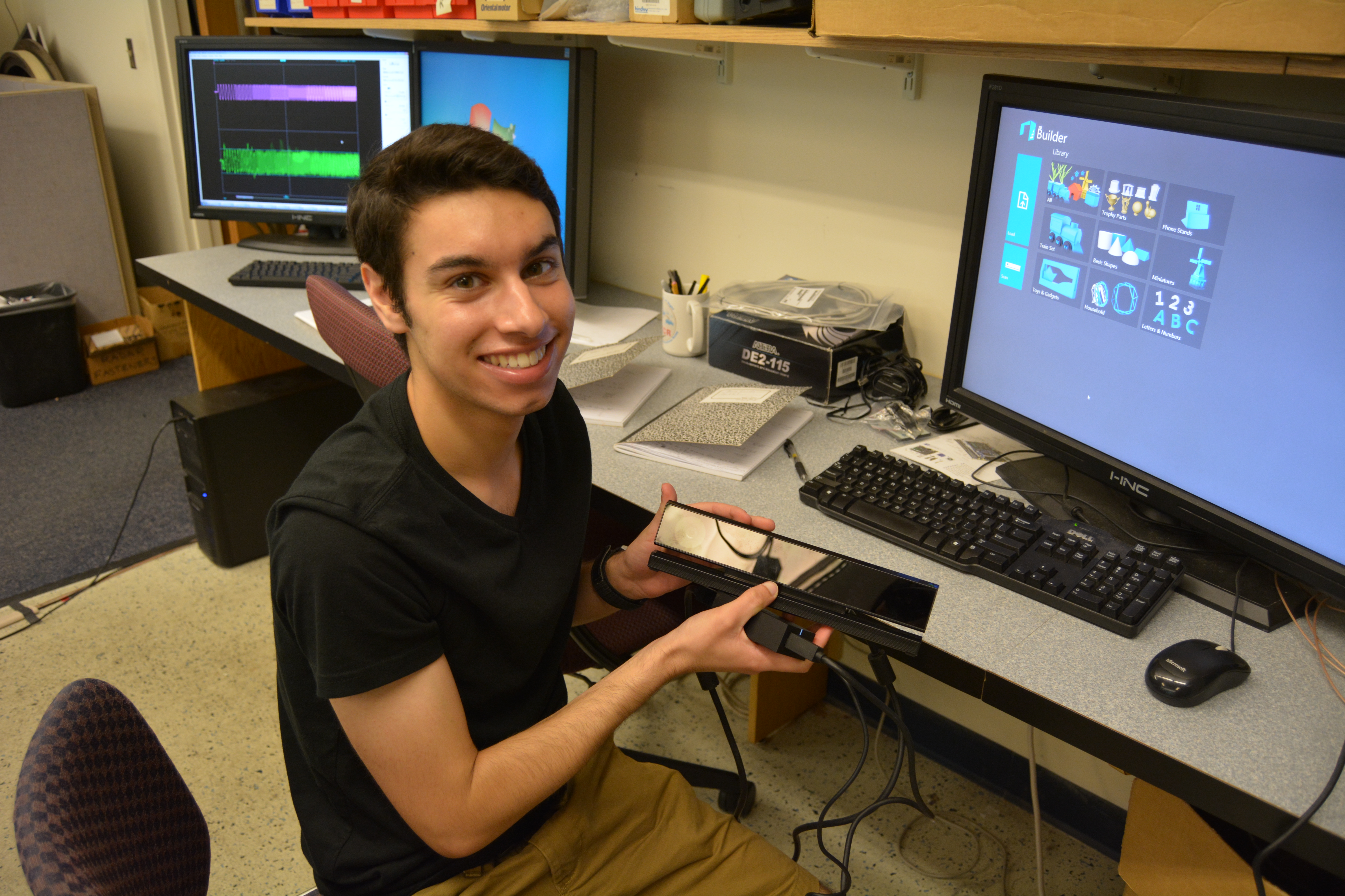
The image to the right is me working on incorporating the Kinect v2 sensor into our LabVIEW code so that our images that we produce will have a ground-truth to compare against.
The code to image with the Kinect was written in Matlab, and then added to LabVIEW as a script.
It works by getting the point cloud of an object using the Kinect's depth sensor and displaying it to the user, complete with a color bar that indicates how far away the object is, in meters, from the sensor.
The Matlab script can be found here, with comments to explain how it works. It is saved as a text file for easy access.
The image to the right shows the hardware setup of the transmitter and reflector shield that is used in the AIT lab to image objects and dielectrics.
In the center of the image, the transmitter (attached to the aluminum arm) sends out electromagnetic waves, which are reflected off of the shield and toward the object (the metal bracket) on the right.
The object then reflects the signals back toward the shield, which in turn reflects the signals once more, this time to the receiver (not in image).
The receiver is moving, gathering data as it sweeps in a semicircle around the curve of the shield. All of the data is then sent through an FPGA to saved folder on a computer.
The data is then processed using Matlab, which plots the signal strength and phases of the waves. With that information, I can reconstruct an image of the object by stacking 2D images of the object together to form a 3D image.
The image to the right shows the hardware setup of the motor that is used in the AIT lab to image objects and dielectrics.
In the center of the image, the transmitter (green circuit board on the right) stays stationary while the receiver (green circuit board on the right) moves in a circular fashion, rotating using the motor.
The receiver picks up the electromagnetic waves bouncing off of the object at different positions and uses the data to reconstruct the image in Matlab.
The motor works by using a LabVIEW VI script to control its speed and direction.
The LabVIEW code is also where the initial parameters of the experiment are set, and through the use of a Matlab file that reads this data and processes it, the experiment can be analyzed.
The image to the right shows the rotary encoder that gathers the position data of the receiver.
It is attached to a wheel that rotates using a motor, such that as the wheel rotates, the encoder sends out two waveforms that are 90 degrees out of phase with each other.
It works by sending its information, the two waveforms that it generates, to an FPGA, which uses a VHDL script to determine whether the wheel is moving clockwise or counterclockwise.
The VHDL script can be found here, with comments to explain how it works. It is saved as a text file for easy access.
 The image to the right is me working on incorporating the Kinect v2 sensor into our LabVIEW code so that our images that we produce will have a ground-truth to compare against.
 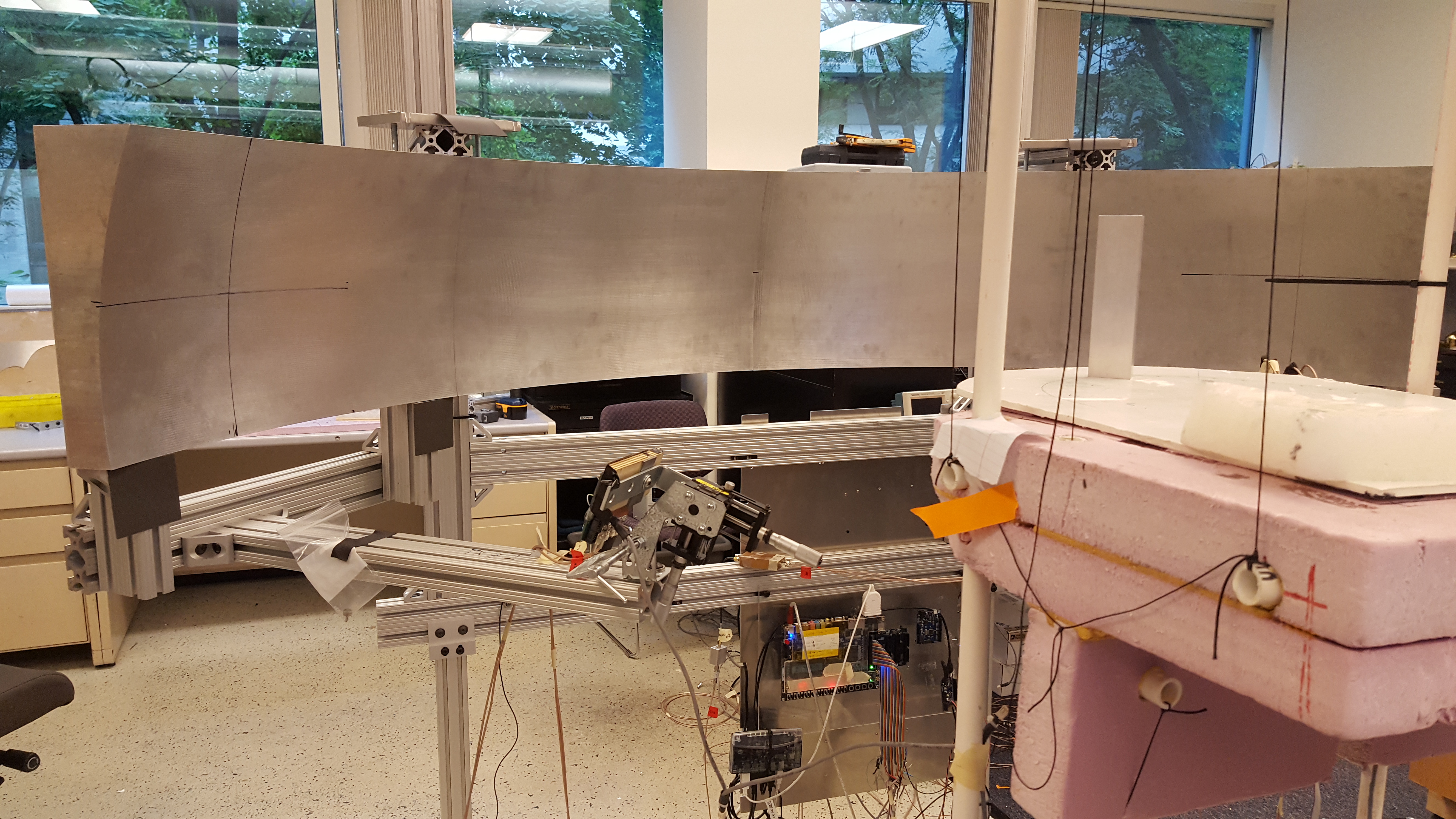 The image to the right shows the hardware setup of the transmitter and reflector shield that is used in the AIT lab to image objects and dielectrics.
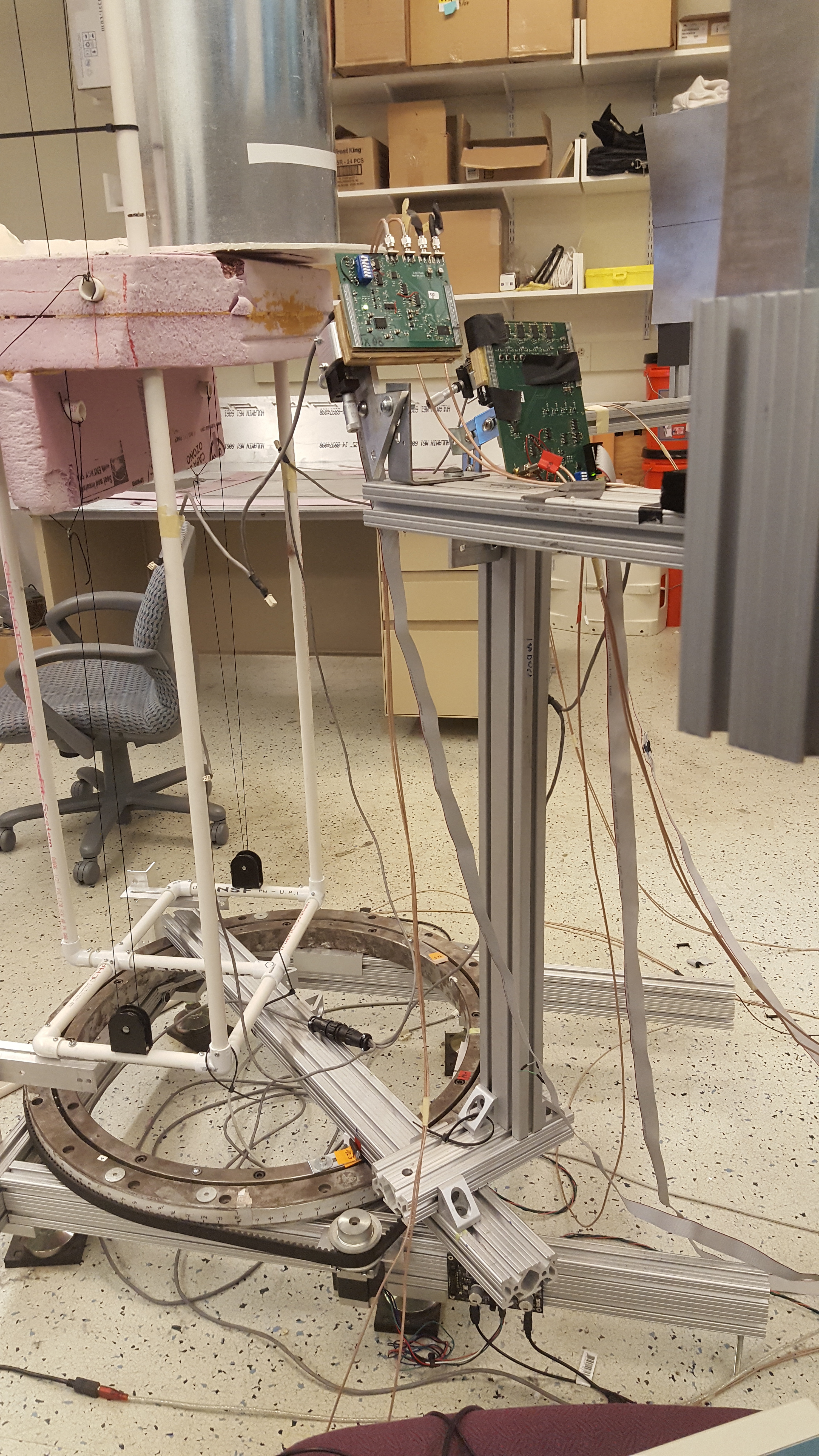 The image to the right shows the hardware setup of the motor that is used in the AIT lab to image objects and dielectrics.
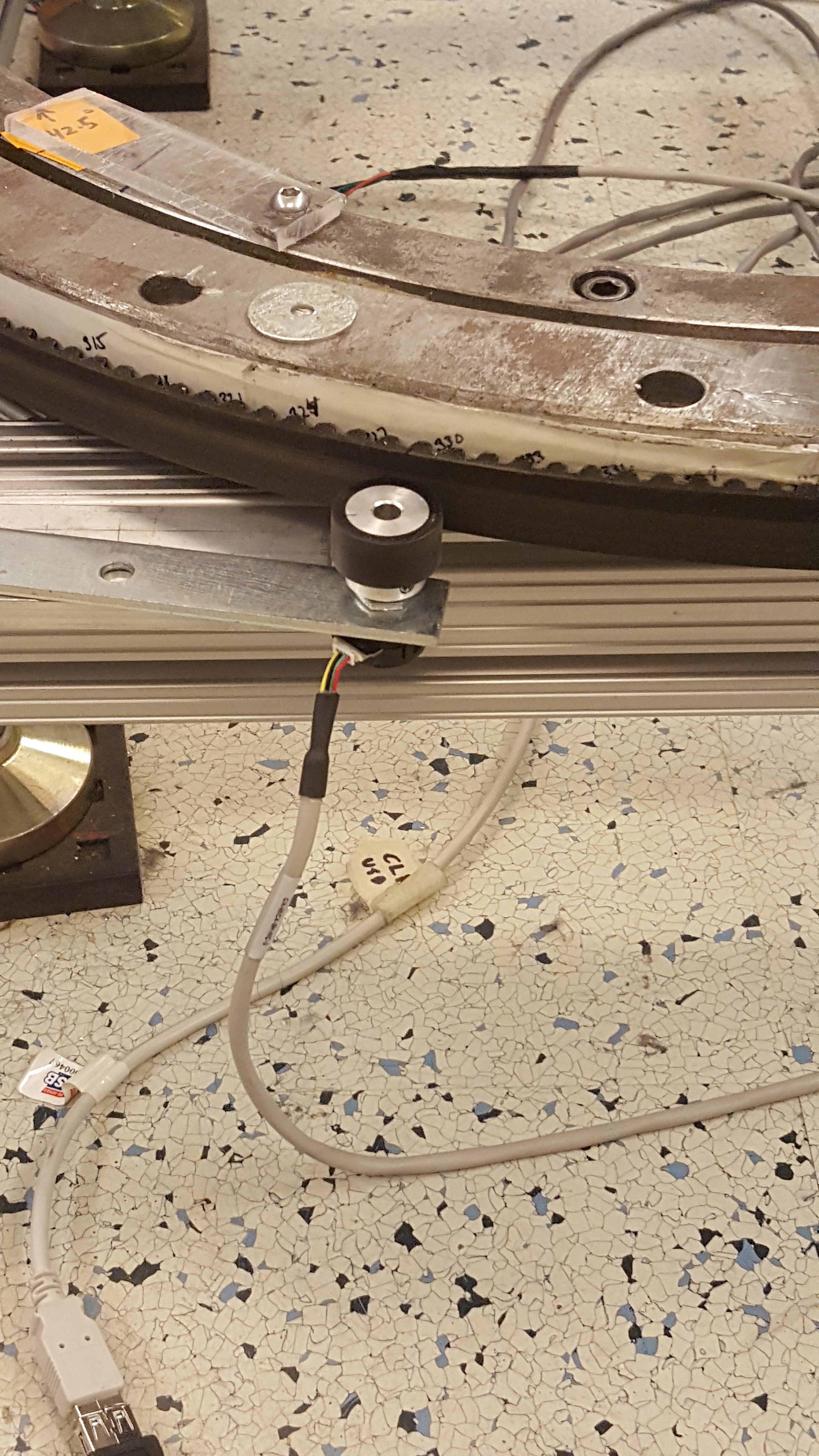 The image to the right shows the rotary encoder that gathers the position data of the receiver.